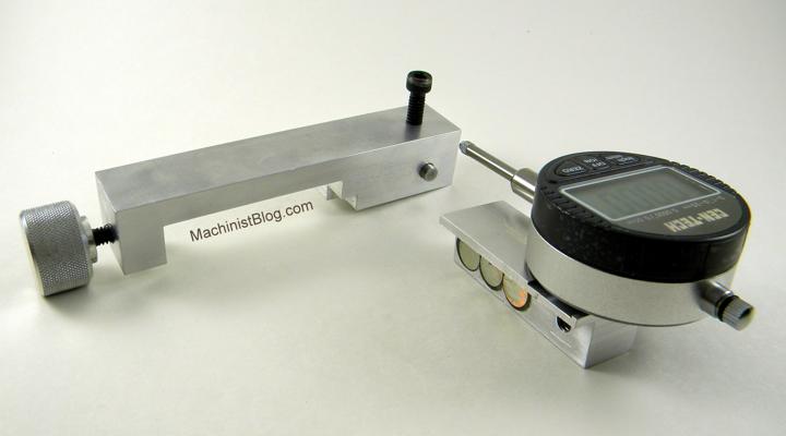
This article describes how I added an easy-to-make DRO (Digital Readout) to the cross-slide of my 7×12 mini-lathe. It uses an inexpensive digital dial indicator that I bought from Harbor Freight for about $25. It works very well and you won’t have to drill any holes in your lathe or disassemble it to install it.
I’ve rarely seen a picture of a mini-lathe with a home-made DRO on it (or any kind of DRO), even though they seem to be fairly common on mini-mills. The ones for mills are usually made from inexpensive digital calipers or scales. I considered using them on the mini-lathe but rejected the idea because there is very little room to put them where they won’t be in the way. They will probably collect piles of swarf, the displays are also likely to be difficult to read and the buttons will probably be located where they will be awkward to push.
Using a digital dial indicator eliminates or minimizes those problems, although it is not a perfect solution. You’ll have to read the display and buttons upside down, which is not really much of a problem because they’re quite large and easy to read.
The indicator has a range of just 1-inch, but my design uses an adjustable bracket that will let you engage the DRO where ever you need it.
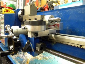
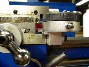
The DRO has two parts. The first is the indicator holder. It’s an aluminum bracket that attaches the dial indicator to the apron using very powerful rare-earth magnets. The magnets are located where they are unlikely to attract steel or iron chips. The second is a stop that clamps to the top of cross-slide and makes contact with the point of the indicator.
The stop can adjust two ways so it can always be made to press against the indicator’s probe, no matter the diameter of your work piece. You just slide it along the top of the cross-slide until it makes contact with the tip of the indicator, which is mounted on the apron. I thought there might be situations, like when working on a very large diameter workpiece, where the stop might not be able to contact the indicator. So I also added an adjustable rod to extend its reach. I now know it’s not needed, although it might if you adapt my design to another lathe.
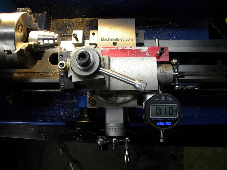
The DRO works very well and it has really improved my productivity. I no longer have to keep stopping to measure how much more metal I have to remove, or keep track of how much I’ve turned the cross-slide knob and then calculate how much more I need to cut.
Most of the time the DRO and the cross-slide dial are in complete agreement, or at least within five ten-thousandths (.0005), which is the resolution of the DI. When they disagree it’s usually because of backlash.
However, I was surprised to find that they would sometimes consistently disagree by forty-five thousandths, and it wasn’t due to backlash. I haven’t fully investigated the cause yet, but I’m pretty sure it’s going to turn out to be axial end play in the leadscrew. It’s a pretty common mini-lathe problem caused by a gap between the head of the leadscrew and the flange it is suppose to turn against. The most common fix is to make a small washer to fill that gap. It’s not really an issue and I’ve learned to trust the DRO.
Construction
This a prototype and not a finished design. I am hoping that others who are smarter and have better machining skills will think of ways to improve it and then share their ideas. That’s why there are no plans for it yet (a shortage of spare time and poor CAD skills also has something to do with it). So, until I get some plans drawn, I hope my photographs will allow you to make your own if you want to. Please let me know if you have any questions and I’ll do my best to answer them.
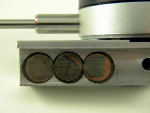
I would begin by making the aluminum bracket that holds the indicator. The hardest part will probably be making the holes for the magnets and then epoxying them so they will be flush with the surface of the bracket.
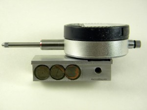
It’s made from a piece of 1-inch square aluminum. I suggest cutting the rabbet (is that the right term?) for the magnets first. Then drill the holes and glue the magnets, leaving some extra length at the rear (the front of the bracket should touch the ways). The extra length will allow you to mount the bracket on the carriage and make sure you like the position of the indicator and before you drill the hole to attach it. You can cut off the extra length later.
By the way, one of my pictures shows the mounting bracket extending way out in front of the indicator’s probe. That wasn’t necessary and I’ve since cut the excess off.
I bought the magnets at a True Value hardware store for about $4. They’re 22mm in diameter and I used a .5-inch center-cutting end mill to make three flat-bottomed holes to mount them in. You need to keep the magnets close together so they won’t extend beyond the corners of the carriage where they could attract ferrous swarf. So don’t make the holes any bigger than they need to be.
When it was time to epoxy the magnets I used a small piece of steel to hold the magnets flush with the top of the holes while the glue dried. You might want to leave one edge of the holes slightly uncovered so any excess glue has a place to seep out. After the epoxy dries you can scrape off any excess with a razor blade.
Make certain that the bracket and magnets are degreased and perfectly clean and dry before you glue them. I used brake cleaner to degrease them and then washed them using dish soap.
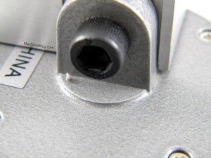
The next step was to mount the indicator on the bracket. Unfortunately, the back of the indicator is not perfectly flat because there’s a small raised area around the mounting lug. I wanted the outer diameter of the indicator to sit flat against the bracket, not just the raised part. So I milled a small recess for it in the bracket. After the recess was milled, I drilled and tapped a 1/4″-20 mounting hole for the indicator. I located it by holding the indicator in place and then marking the hole with a transfer punch.
I’m not certain the recess is necessary and the next one I make may not have it. If you decide to mill one then don’t do what I did and put it on the side instead of the top. Also, don’t drill the mounting hole and then decide to clean up the top of the bracket with a fly-cutter to make it look prettier for pictures. That’s why there’s a small gap between the indicator and bracket. 🙂
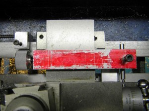 The movable stop that slides on the top of the cross-slide is also easy to make. It’s made from another piece of 1×1-inch aluminum that’s milled so it fits over the top of my mini-mill’s cross-slide. The small notch in one of the corners is there so it won’t contact one of the gib adjustment screws.
The locking mechanism is made from a knurled knob that was pressed onto the head of a 1/4″-20 socket head cap screw. The next one I make is going to use a slightly larger diameter screw with finer threads because I think it will tighten more securely. Also, I had to add a small neck to the knob so it would clear part of the apron. The next one I make won’t need it.
As I mentioned earlier, I don’t think the adjustable-length rod on the prototype is necessary and you can always add it later if you want. Just mount the DRO on the lathe, put a piece of masking tape on the stop and push the indicator’s plunger against it. It will leave a mark that you can center punch and drill.
Improvements and Other Ideas
- Reading the display upside down is not hard, but it would be nice if it could be turned around to face the right direction.I was hoping that the top half of the indicator, which has the LCD display and buttons, was connected to bottom half by wire, so it could be turned around to face a different direction. But it can’t be done because it is attached almost directly to the circuit board in the base through a small conductive spacer.I have been wondering if it might be possible to turn it around by modifying the internal spring, or adding an external spring, so the plunger operates in the opposite direction. That would also probably require shortening the longer shaft at the bottom of the indicator, lengthening the one at the top, and swapping the tips around. Reading the display upside down has not really been a problem, so I don’t know when I’ll get around to exploring this modification.I’ve learned that Mitutoyo makes DIs with displays that can be turned 330-degrees, but they’re pricey. Please let me know if you know of any others with the same feature. I’d like to find an affordable one with a rotatable display, a mounting lug on the back, a 1.0-inch range, and a resolution of .0001 inches.
- The magnets have held the indicator very securely in place. I haven’t experienced a problem with it slipping and affecting the measurements. But it could, and it could easily be prevented by milling a stop on the bracket to prevent it from sliding backward.
- I used 1-inch square aluminum because I had some on hand. But it could probably be made out of smaller stock, to save some money on material costs.
- One thing I like about digital calipers is that you can zero them at your target dimension. Then when you make a measurement the caliper will automatically tell you exactly how much more material you still have to remove. You can do that with my design, but a dial indicator is more difficult than a caliper to zero exactly where you want it. I have been wondering if some kind of mechanism could be made to make it easier.
- I’m not sure, but it’s possible the indicator could be damaged by pushing the plunger in too far. It could be prevented by adding a stop on the mounting bracket that would make contact with the cross-slide stop before that happens. However, it could reduce the indicator’s measuring range if it’s not done right.
Parts List
- Harbor Freight Digital Dial Indicator: They normally cost about $30. I hadn’t seen them on sale in a while so I bought one at my local store with a 20% off coupon I found in a magazine.
- (3) 12mm x 3mm Neodymium disc magnets: I’ve found them True Value hardware stores and on Amazon.
- 1-inch square 6061 aluminum bar stock about 12-inches long:a 1.0 x .75-inch piece would also probably work.My indicator holder is pushed up against the ways so it will always be in the same position. It needs to be 1-inch high to make contact, but there are other ways to achieve the same thing. For example, you could add a notch that would fit the corner of the apron.
- Epoxy to glue the magnets: the epoxy will flow better if it’s warm and a hair-dryer can help with that.
- 1/4-20 socket head cap screw: To attach the dial indicator to the bracket.
- 5/16-24 socket head cap screw: I made the original locking knob using a 1/4-20 SHCS but I think one with a slightly larger diameter and finer threads will work better.
- Locking knob: I knurled a piece of 1.25-inch diameter aluminum to make mine, but you could use something else or buy one that’s already made.
I’d like to know what you think of my idea and I’ve tried to making leaving a comment as easy as I can without leaving the door wide open to spammers. Just write your comment and give us your e-mail address. If it’s not spam we’ll approve it, register you as a user and send you a password which you can change if you want.
— Rob R.
Is there a reason all the images say “I steal images from machinistblog.com”? They show up both on my Google reader, and on your site.
The “I steal…” image is coming from MachinistBlog, but I don’t know why you’re seeing it. A few weeks ago I found that a shady website had hot-linked some of my images. So I did some research and found that I could modify my .htaccess file so it would display a different image instead. Then I made a substitute that would give me some free publicity. It appears that the solution is either not fool-proof or I did something wrong.
The offending web site is gone, so I’ll remove the code so you can see the images. (Let me know if you’re still having a problem)
I’d appreciate it if anyone could tell me why this happened. The modification I made is suppose to be widely used. — Rob
Since googlereader was requesting the images (instead of machinistblog.com) your htaccess worked and blocked them.
Later when anonymous tried to access the site directly, their browser had the images cached already, so the browser displayed the cached images instead of re-downloading them from your site.
You could add googlereader as a “trusted” domain to your htaccess code to fix this.
OR, if you want to continue to block google i suggest appending a constantly updating timestamp to all your images. For example lathe.jpg?epochtime=1262816405
Hello Rob,
This looks like a great idea. I was wondering if you have finalized the prototype and made plans for it to download? All the materials needed in your bill of work,minus the aluminum is available at your local Harbor Freight,including the rare earth magnets.I have a Central Machinery 7 x 12 that’s just begging for an upgrade such as this. I was going to purchase the DRO 2 axis kit from LMS,however I do not like the idea that it hinders the swing travel of the compound rest.
-Rick
Nice idea.
For longer travel I succeeded in applying a digital caliper without mutilating the lathe
with the aid of a magnetic base and a small vise.
The vise is magnetically held by the base, and the “tail” of the caliper is held in the vice.
it is one-way, you have to push the caliper back by hand,
but on the other hand it is easy to set up AND
measures the combined actions of saddle and compound.
picture here : http://i625.photobucket.com/albums/tt336/raalst/DSCN0445.jpg
another caliper takes care of the cross feed.
this required drilling one of the caliper beaks and grinding off parts of both beaks.
grinding was ok, but drilling was a nightmare.
It also took me two M3 holes in the carriage.
(the first hole was too close and jammed with the gib strip nuts, duh!)
[img]http://i625.photobucket.com/albums/tt336/raalst/DSCN0448.jpg[/img]
I’m still thinking about how to keep the end of the calipers from swivelling.
I have a workaround (a bit of scrap between caliper and carriage),
but I like something more sturdy.