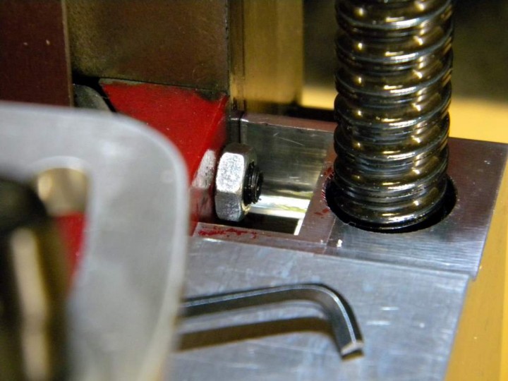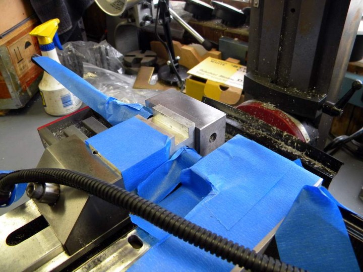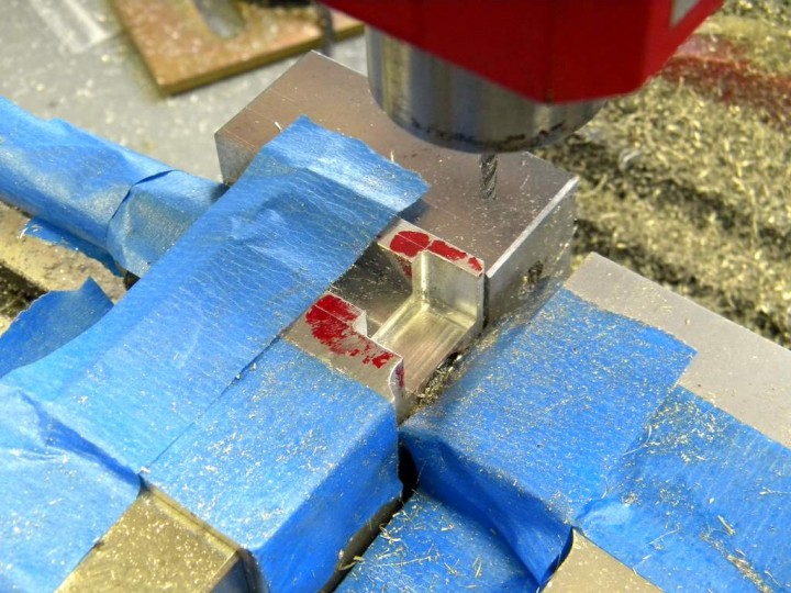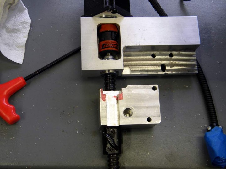
Here’s a modification I made to the Z-axis ball screw mounting bracket on my Sieg X2 (Harbor Freight) mini-mill. My CNC conversion kit was made by CNC Fusion and their design does not allow you to adjust the top gib screw without removing the column from the base and sliding the head half way off of it, which is necessary to get at a large 10mm bolt that holds it from the inside of the spindle head (along with 2 smaller bolts on the outside). My post about removing the X2’s intermediate gear has some photographs that will show you how much work it takes.
The bracket actually covers up the top two gib screws and there’s not much you can do about the second one except to adjust it properly before you install the ball screw and then hope you never need to adjust it again. To make it accessible you’d have to remove metal near where the ball screw nut is attached and I don’t think you can do that. But there’s nothing to prevent you from making a bigger opening so you can adjust the top gib screw with a shortened 3mm hex wrench. I also made it big enough so I could get a wrench or at least some needle-nose pliers in there to loosen or tighten the lock nut. If I’d been able to wait a week or so I would have eliminated the lock nuts altogether by ordering self-locking ones from LittleMachineShop.com.
I have two mills, which made it possible for me to make this modification. If you don’t have that luxury you might want to consider doing it before you begin converting your mill to CNC. The original opening was about .60 wide and .38-inches deep. It’s now .94-inches wide and .55-inches deep.
I’m not sure, but there may also be another solution and that would be to eliminate the internal bolt by replacing it with more external ones. That would allow you to quickly and easily remove the Z-axis ball screw so you could have full access to all the gib screws. I think CNC Fusion did it the way they did so their customers would not have to drill and tap any holes in the spindle head. Their design avoids that by reusing the holes used by the height adjusting wheel and mechanism. Of course if you used more external bolts you’d have to put them where they wouldn’t interfere with the gears inside the head. You’d also have to make certain they could handle the weight of the head, which I think is about 12 pounds. That’s one advantage the big internal bolt has.
I know this is a boring post for most of you. But I”m hoping it will help others who also have one of these CNC conversions kits.
More Photos


I came up with this:
1- move the dang electrical box so it’s flush on the gib side of the column- this ain’t easy since it has two ground screws in the column – I’m using a piece of wood, sloting it so that a wire can be brought out to the slot in the moved enclosure, then screwing the box on to the wood… it’ll help absorb some shock too…
2 – Go to the auto parts strore and get some hex screws 6mm x 20 – 1mm pitch
3 – lathe the end down to match the gib slot – use a soft jaw and mod it like this:
http://home.comcast.net/~ajawam5/DSCN2259.JPG
4 – replace the socket heads with the hex screws – use a bit of 242 locktite (just a bit) after cleaning out the crap in the hole
http://home.comcast.net/~ajawam5/x2gibscrew1.jpg
http://home.comcast.net/~ajawam5/x2gibscrew2.jpg
Viola – adjustable gib on the Z
More pic’s – check out the GETO (Government Engineering and Technology) temp bellows for the screw (a bike innertube)
http://home.comcast.net/~ajawam5/DSCN2280.JPG
http://home.comcast.net/~ajawam5/DSCN2286.JPG
http://home.comcast.net/~ajawam5/DSCN2288.JPG
How I routed the chassis ground:
http://home.comcast.net/~ajawam5/DSCN2292.JPG
I’m currently using a arduino and a stepper from Anaheim (built in drive) to use it for now, eventually I’m doing this:
http://home.comcast.net/~ajawam5/zhandgear.jpg
I want a manual mill – I want to use a trig book and slide rule ( already have a small CNC)… I swear the Chinese mills are built so we can’t build weapons to take over China…the manual z rack sucks
This will go where the stepper is…the bevel is to move quick, the single worm slides over (threaded rod not shown yet) to fine feed/lock the Z ball screw..
I’ve just about had it with the inability to adjust the gibs, too, and it occurred to me that it seems the best solution would be to just move the ballscrew to the left side of the mill so it doesn’t interfere with the gib screws. Yeah, you have to fabricate mirrored version of the motor and ball nut holders and drill new holes in the head, but I’d rather do that once than live with the pain.